
New South Wales Signalling in Trainz with the R51 Signal Kit
|
Contents
Using the R51 Signal Kit
|
Diagram Notes
A number of diagrams are used throughout the tutorial to depict how signals and targets may be placed. In most cases, NSW Single Light signals are used but the same setups can be applied to Double Light signals (see the section “Signalling in NSW - Types of Signals”).
Signals which are displayed as an outline are representative of the type of signal which can be used in that scenario. Signals displayed in colour are used to show specific signal aspects for the example being depicted.
Using the R51 Signal Kit
The R51 signal kit provides a wide range of signal assets to suit NSW railways. The following guides will help you set up the signals and use them on your routes. It is primarily aimed at CTC signalling as this is the main method of safe working covered by the R51 signal kit however some information is provided for Train Order working as well.
Controlling Signals
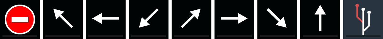
Targets are used to allocate specific routes that a signal may control. They are mainly used for signals with turnout units or route indicators, and can also have a direction associated with them. The main targets you'll need are the direction targets by Bloodnok which are available on the download station, or built-in depending on your Trainz installation. The Bloodnok targets have a black background, while the R51 targets have a dark blue background.
Route Targets
These inform the signal as to which route they should display.
These inform the signal as to which route they should display.
- Danger (“Sig T Danger” by Bloodnok)
- Left 1, 2 and 3 (“Sig T Feather Left” by Bloodnok)
- Right 1, 2 and 3 (“Sig T Feather Right” by Bloodnok)
- Straight (“Sig T Feather Straight” by Bloodnok)
- Nameable (“Route Override” by Ranger_51)
Modifier Targets
Modifier Targets are used to modify a signal's behaviour when set to a specific route, and allow custom signal indications. These targets include a white border and small plus-sign in the top left, indicating that they are used in addition to other targets.
Modifier Targets are used to modify a signal's behaviour when set to a specific route, and allow custom signal indications. These targets include a white border and small plus-sign in the top left, indicating that they are used in addition to other targets.
- Advanced Warning
- Low Speed
- High Speed
- Shunt
- Shunt Limit
- Elec Train Stop

Invisible/Fixed Signals
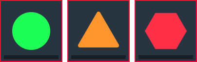
There are also 3 invisible signals which may be useful in testing and building routes. These targets have a red border.
There are also 3 invisible signals which may be useful in testing and building routes. These targets have a red border.
- Clear
- Caution
- Stop
|
Configuring Routes Standard Turnout
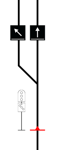
In the example, a left diverge indication will be shown when the points are set for the track on the left. High Speed Turnout
In the example, a diverge indication will be given when the points are set for the left track and, provided the next signal is at least MEDIUM, the diverge signal will be able to show CLEAR. The Mi will illuminate to show the route that has been set. Low Speed Turnout
In the example, the signal will show a LOW SPEED indication when the points are set for the left track. Note: A low speed indication may also be used when the overlap area is occupied by another train. This is more common with Double Light Colour Light (DL) signalling in areas with higher levels of rail traffic. For this setup, no targets are required. Shunting Routes
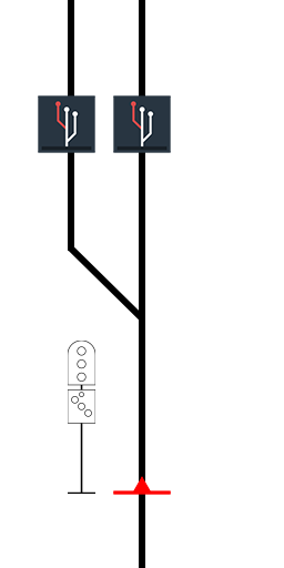
Note: Most of the time you will not need the Shunt Limit target. However, if the shunt indication does not show as expected, then placing a Shunt Limit target after the direction target may help. This will happen if there are no more signals on the track or if the next signal is too far away. The Shunt Limit target also acts as a track mark and can be a useful asset for navigating when in driver mode. Note: Standalone shunting signals do not need the Shunt target as the only type of route they can display is a shunting route. The exceptions to this are the intermediate shunting signals. In the examples, the signal will show a SHUNT indication when the points are set for the left track. Route Override Target
To setup:
Blocking Routes
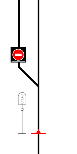
In both examples, the signal will display STOP when the points are set for the left track. Other Targets Advanced Warning
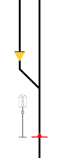
In the example, the bottom signal is showing PRELIMINARY MEDIUM because the next signal shows MEDIUM and there is an Advanced Warning target between them. Electric Train Stop
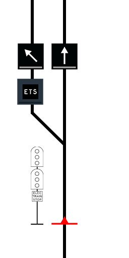
In the example, the Electric Train Stop indicator will flash the words “ELEC TRAIN STOP” when the points are set for the left track. |
|
Route Indicators
Signals may be fitted with one or more additional indicators. These will display information about the route which has been set.
Turnout Repeater (Indicator)
Signals may be fitted with one or more additional indicators. These will display information about the route which has been set.
Turnout Repeater (Indicator)
- These provide warning of a turnout ahead.
- They cannot be directly controlled. Instead, they get their direction from the next diverge signal.
- The Turnout Repeater can give indications for a diverge signal up to 2 signals away. See the diagram for examples.
- Display letters or numbers referring to the route which has been set.
- Controlled using direction targets.
- It can be configured in the signal’s properties window.
- These are only fitted to Single Light signals and Mainline Indicators.
- Controlled using direction targets.
- They display the turnout route as either left or right angled lights.
- The small route indicator is used for subsidiary routes such as Shunt and Low Speed.
- Controlled using direction targets.
- It can be configured in the signal’s properties window.
In the above example, the turnout repeater will illuminate when signal 15 is set for the diverging track.
Stand-alone Route Indicators
Stand-alone indicators are intended to be used with signals which are not already fitted with one, including signals not from the R51 Signal Kit. Whilst I’m not aware of any examples used in NSW these have been added to give route builders some creative freedom in signalling their routes.
There are two ways you will need to place the indicator depending on the signal you are pairing it with.
If the signal can display multiple routes, place the indicator just before the signal. If the signal can only display a single route, place the indicator after the signal and place direction targets as needed.
The example on the left shows a signal (“NSWGR semaphore shunt signal, ShA ShA, lower quadrant, dwarf, mechanical, ground mount, pull to rear” by Elstoko) which can display multiple routes using the direction targets. The SRI indicator is placed just before this signal. The example on the right shows a signal (“NSWGR semaphore shunt signal, shA, lower quadrant, dwarf, mechanical, ground mount, pull to front” by Elstoko) which can only display a single route. The SRI indicator is placed just after the signal and direction targets are placed on the appropriate tracks.
Signal Properties
Signals in the collection have a number of customisable features accessed via the properties window.
Display Name
Signals need to know where trains are so they can give the correct indications. The search distances control when certain indications can be given.
Signals in the collection have a number of customisable features accessed via the properties window.
Display Name
- The display name allows you to set a different name on the nameplate than the one given to the asset in Trainz.
- The default is “Not Set” which will use the same text as the signal name.
- This allows you to change how far the signal is placed from the track.
- Negative values place the signal on the left, positive values on the right.
- On some signals, an arrow sign will appear when it is repositioned to the opposite side of the track from its default position.
- Setting this value to 0 will reset the offset to the default value.
- The grey numbers on each side show the minimum and maximum values.
- This section provides information on what aspects and indications the signal is capable of displaying.
Signals need to know where trains are so they can give the correct indications. The search distances control when certain indications can be given.
- Outer Approach - This applies to controlled signals. If no trains are approaching within this distance then the signal will be held at STOP.
- Inner Approach - This applies to subsidiary indications. Trains must be approaching within this distance before the signal will show SHUNT or LOW SPEED.
- Overlap - This provides a safety buffer and is measured from beyond the next signal. There must be no trains within this distance for the signal to clear. It is ignored for Shunt and Low speed indications.
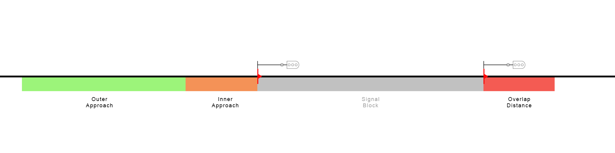
In the above image, the green section shows where the outer approach zone is measured from, orange for the inner approach and red for the overlap. For a signal to clear, the grey zone must also be clear of trains.
Route Table
For signals fitted with route indicators, the Route Table allows you to set the text to be displayed for each route. Only the letters A to Z and numbers 0 to 1 are supported. A “-“ (hyphen) may also be used as a blank space.
Route Indicator Settings
Most indicators have multiple style options which can be changed by clicking the arrows either side of the icon.
Style Settings
For signals fitted with route indicators, the Route Table allows you to set the text to be displayed for each route. Only the letters A to Z and numbers 0 to 1 are supported. A “-“ (hyphen) may also be used as a blank space.
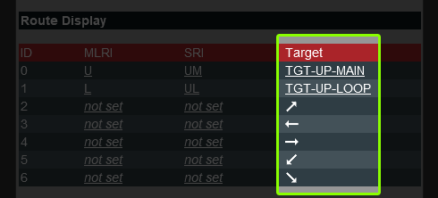
- ID - This shows the order of the routes. 0 is always the default route.
- MLRI - This column is where the text for the Mainline Route Indicator is set. “not set” means no text will be displayed.
- SRI - This column is where the text for the Small Route Indicator is set.
- Target - By default, this column shows an arrow indicating which direction target to use for that route. Clicking on the arrow allows you to enter the name of a Route Override target instead.
- Note: A light blue arrow indicates the signal can repeat the direction given by the signal ahead. This is used on Co-acting and Indicator signals.
Route Indicator Settings
Most indicators have multiple style options which can be changed by clicking the arrows either side of the icon.
- MLRI changes the large route indicator
- SRI changes the small route indicator
- TOU changes the Turnout Unit
- SUB changes the subsidiary indicator lamp.
Style Settings
- Options for changing the head background shape, hood style and lamp style can be configured here.
- Clicking “Apply to All” will copy the style settings to other signals of the same type.
- “Background” changes the shape of the lamp background for the upper, lower and marker lamp heads. “Hood” changes the shape of the lens hood. “Lens” switches between incandescent or LED lamps.
- Some signals have an additional option called “Misc”. This is not included when “Apply to All” is clicked.
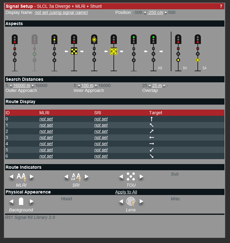
This image shows an example of the signal properties. The aspects, route table and a number of style options are available.
Signalling In NSW
Types of Signals
Signal Forms
There are currently 4 main forms of signalling covered by the R51 Signal Kit
SL and DL Automatic Signals
Automatic signals are not directly controlled by a signaller. They operate automatically and cannot be used to protect hazards such as crossings and points.
The upper and lower heads (or marker lamp) are offset from each other.
Signal Forms
There are currently 4 main forms of signalling covered by the R51 Signal Kit
- Single Light (SL) - Uses a single lamp head to display the main running aspects. Common in the suburban areas of the rail network or areas with low levels of rail traffic.
- Double Light (DL) - Uses two lamp heads to display the main running aspects. They are effectively a combined Home and Distant. The upper head gives authority to enter a section and the lower head provides warning about the next signal. Common in inner city parts of the network and areas with high levels of rail traffic.
- Shunting (SH) - Stand-alone and subsidiary signals which authorise shunting movements around yards. Stand-alone shunt signals may have horizontal(SH-H) or vertically aligned (SH-V) lamps while subsidiary shunt signals have a single yellow lamp and are attached to the same post as regular signals.
- Mainline Indicators (MLI) - These are used as part of Train Order working. They are common in regional and country parts of the network.
SL and DL Automatic Signals
Automatic signals are not directly controlled by a signaller. They operate automatically and cannot be used to protect hazards such as crossings and points.
The upper and lower heads (or marker lamp) are offset from each other.
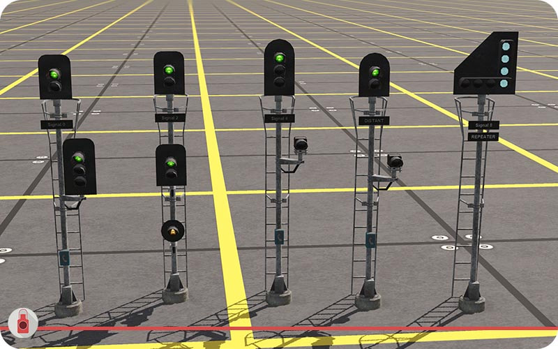
From left to right; DL 2a3a Auto, DL 2a2a Auto/Controlled, SL 3a Auto, SL 2a Distant, 2p Repeater.
Automatic signals have the following designations:
Automatic
Automatic
- A standard automatic signal used to split long sections of track into smaller blocks, allowing more trains to travel through the section.
- These signals operate as automatic signals but can be switched to controlled mode if needed.
- This may be used in places where, for example, an emergency crossover is installed which would not normally be used or a rarely used branch line merges with the main line.
- They are fitted with an “A” light that illuminates when the signal is in automatic mode.
- In Trainz, this signal functions as an automatic signal unless it has been forced to display a specific aspect.
- These signals provide advanced warning of the next signal ahead.
- They cannot typically display STOP.
- They are fitted with an identification plate with the word “DISTANT” on them.
- Repeaters provide early warning of the next signal ahead.
- They are fitted with an identification plate with the word “REPEATER” on them as well as the name of the signal they are repeating.
- These types of signals can have many forms.
- Co-acting signals show the same aspects as the parent signal and are used when visibility of the parent signal may be obscured.
- Indicators perform a similar function but may show the aspects in a different form.
- These signals are fitted with an identification plate with the word “CO-ACT” or “IND” as well as the name of the parent signal.
- In Trainz, if you place two signals close together, the first signal will repeat the indication of the next and thus act like a Co-acting or Indicator signal.
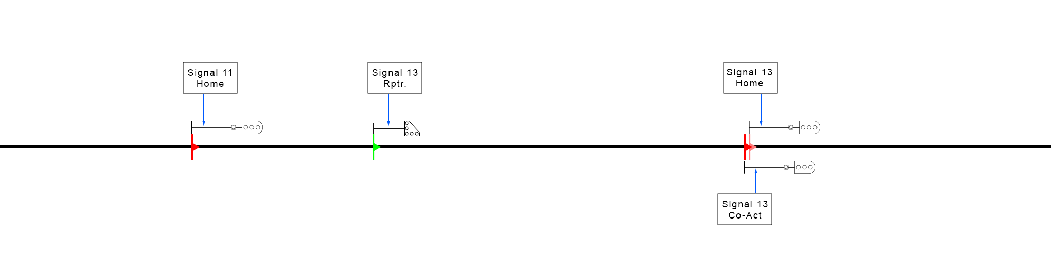
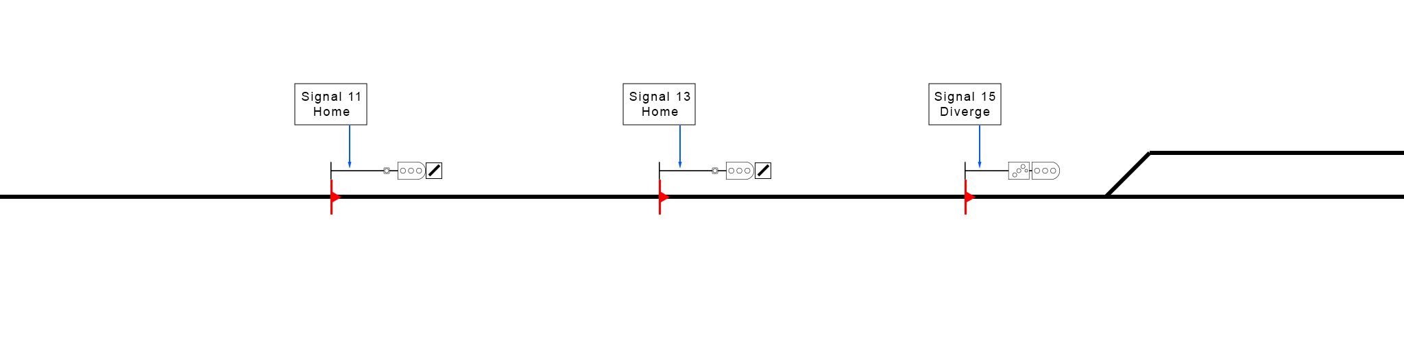
This example shows two types of indicators, an LED Repeater signal and a co-acting signal. “Signal 13 Rptr” will provide a clear indication when “Signal 13 (Home)” is displaying clear. Because it is an indicator signal, “Signal 11 (Home)” will ignore it. “Signal 13 (Co-Act)” is a regular signal which has been placed close to the home signal (as shown by the placement of the red helper icons). This means it will repeat the indications given by “Signal 13 (Home)”.
SL and DL Controlled Signals
Controlled signals are directly controlled by a signaller and protect hazards such as crossings and points. They will remain at stop until a train is approaching.
The upper and lower heads (or marker lamp) are in line with each other. They may also be fitted with subsidiary indicators.
Controlled signals are directly controlled by a signaller and protect hazards such as crossings and points. They will remain at stop until a train is approaching.
The upper and lower heads (or marker lamp) are in line with each other. They may also be fitted with subsidiary indicators.
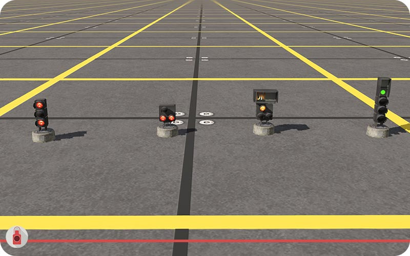
From left to right; SL 3a Home/Start, SL 3a Diverge (with route indicators), SL 2a Home + Shunt, DL 2a3a Home + Shunt, DL 3a3a Diverge + Shunt.
Controlled signals have the following designations:
Accept
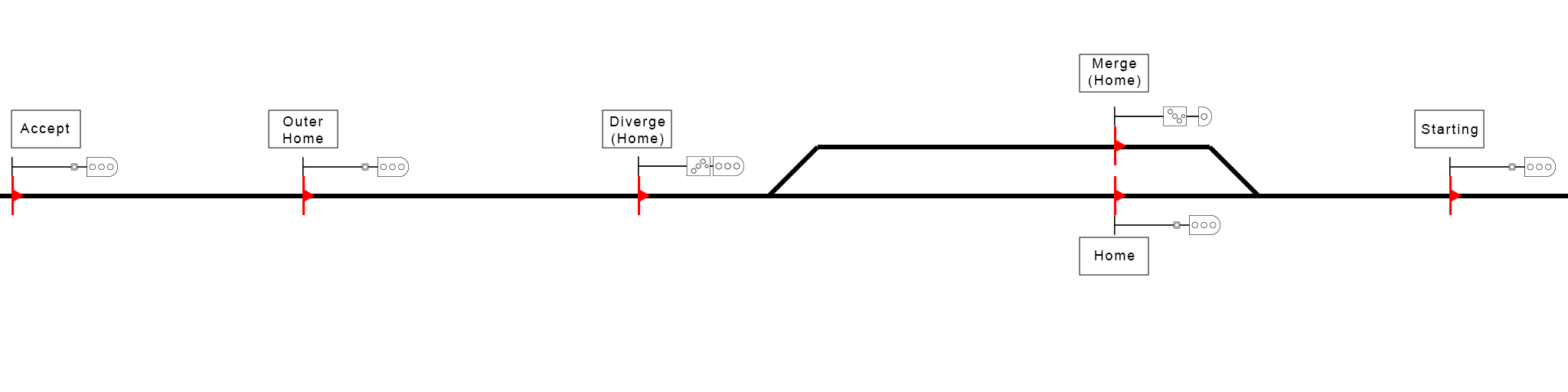
The diagram below shows an example of how these types of signals should be placed. Note the Merge signal at the end of the loop could also be replaced with a regular Home signal.
Accept
- These signals give authority for trains to enter a controlled section. i.e. The signaller accepts trains into the controlled section with this signal.
- They are fitted with an identification plate with the word “ACCEPT”. In Trainz, this may be found as a separate asset to be placed on any signal.
- These signals are placed before the signal protecting the hazard.
- They are fitted with an identification plate with the word “OH”. In Trainz, this may be found as a separate asset to be placed on any signal.
- A signal which protects a hazard such as a level crossing or platform.
- Diverge signals are Home signals which protect a set of diverging points or crossovers.
- Merge signals are Home signals used at the end of loops or tracks which must merge back with the main line.
- These signals require route targets to be placed so they can show the correct diverge indication.
- These are the last signals in a controlled section and provide authority for trains to leave the section. i.e. it gives trains the authority to start their journey towards the next controlled section.
The diagram below shows an example of how these types of signals should be placed. Note the Merge signal at the end of the loop could also be replaced with a regular Home signal.
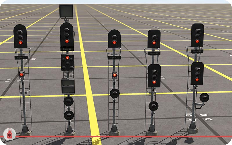
Shunting Signals
Shunting signals authorise movements around yards as well as allowing trains to enter sections of track which may already be occupied.
Shunting signals authorise movements around yards as well as allowing trains to enter sections of track which may already be occupied.
From left to right; SH-V 2a, SH-H 2a, SH-H 2a 2r, SH-V 3a Int.
Shunting signals have the following functions:
Stand-alone
Stand-alone
- A standard shunting signal.
- Mounted on the ground or a short post. These can be in horizontal (SH-H) or vertical (SH-V) forms.
- In Trainz, these signals do not need the shunt target to operate correctly.
- When fitted to the post of a running signal, shunt signals are known as subsidiary shunt signals.
- They can be used to authorise train movements into sections of track which are already occupied.
- These are stand-alone shunting signals which are placed in between running signals.
- They break up a section of track for the purpose of shunting movements only.
- They can display regular mainline aspects in addition to shunting aspects.
- In Trainz, these signals will need the shunt targets if you want them to show shunting aspects.
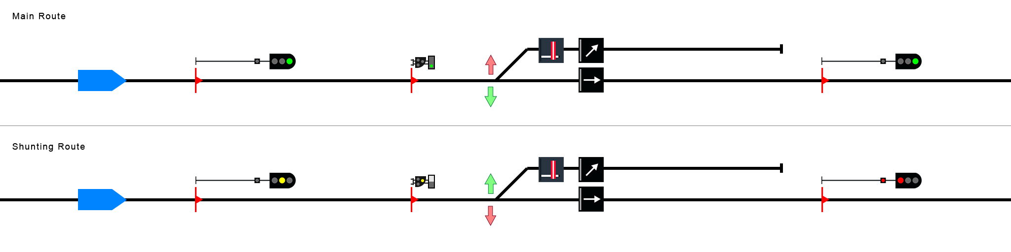
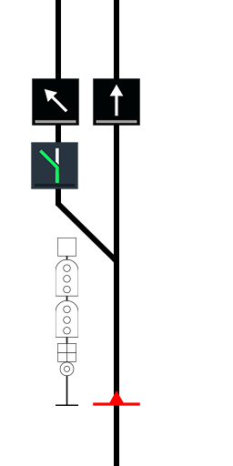
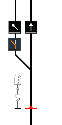
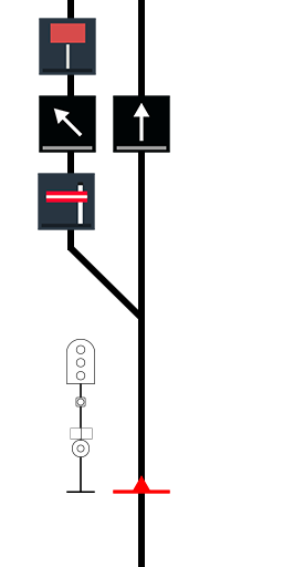
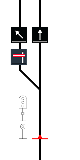
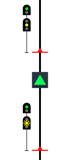
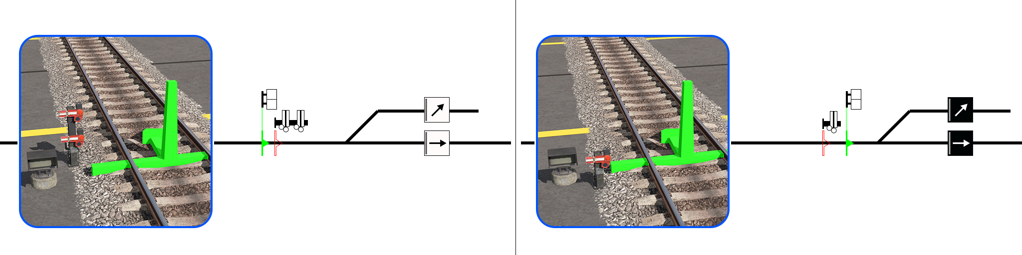
Example: The top image shows the route set for the main line and the intermediate shunt signal displaying CLEAR. The bottom image shows the route set for the dead end siding (shunt route) with the intermediate shunt signal displaying SHUNT. The blue block represents an approaching train.
Mainline Indicators
Mainline indicators are used in regional areas that use Train Order Working. In real life, these indicators are not technically signals and do not authorise train movements. Instead they simply provide information about the route that has been set. In Trainz, these function in much the same way as Single Light signals.
Mainline indicators are used in regional areas that use Train Order Working. In real life, these indicators are not technically signals and do not authorise train movements. Instead they simply provide information about the route that has been set. In Trainz, these function in much the same way as Single Light signals.
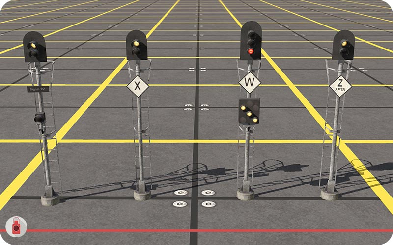
From left to right; MLI Starting, MLI Indicator, MLI Diverge/Merge, MLI Repeater..
Mainline Indicators have the following functions:
Starting
Starting
- Give authority for trains to enter a section controlled by Train Orders.
- They are the same as regular 2-aspect Single Light signals but use a white light for CLEAR instead of a green one.
- Indicate the route is set.
- They are commonly placed either side of a level crossing and indicate that the level crossing equipment is working and that trains are allowed to pass.
- They are fitted with a diamond identification plate with a single letter.
- For MLIs at level crossings, this is typically “W”, “X”, “Y” or “Z”.
- These protect turnouts.
- They are fitted with a Turnout Unit.
- These signals require route targets to be placed on the track so they can show the correct diverge indication.
- These repeat the state of the next MLI.
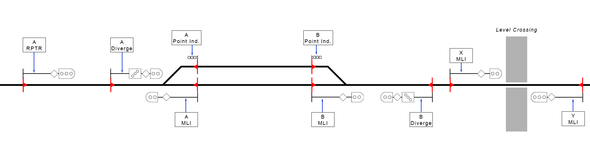
Example: The above diagram demonstrates a simple loop and level crossing arrangement using MLIs. MLI Indicators are used on the mainline with ground Point Indicators used on the loop.
Aspects
Below are the different signal aspects or indications which can be given. They are shown as:
NSW INDICATION
Trainz Indication
Below are the different signal aspects or indications which can be given. They are shown as:
NSW INDICATION
Trainz Indication
- Meaning
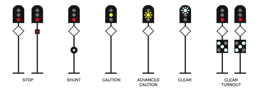
Single and Double Light Signals
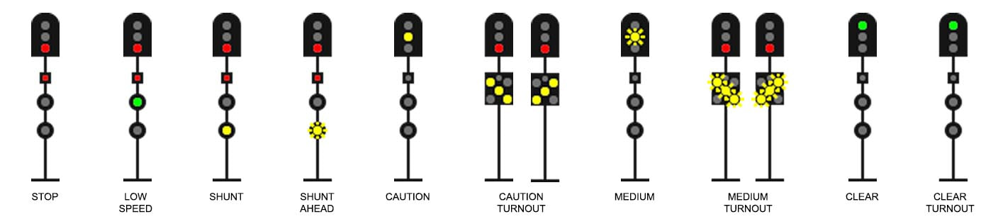
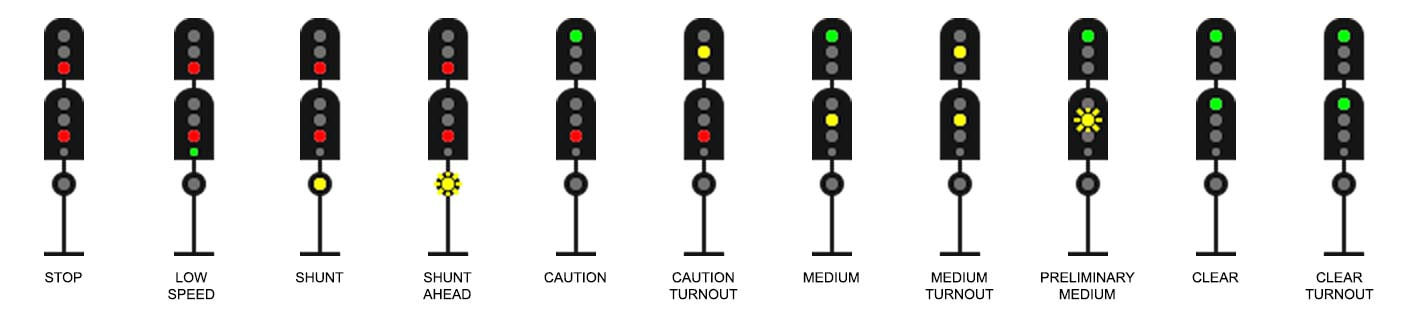
STOP
Stop
LOW SPEED
Stop then Continue
SHUNT
Medium
SHUNT AHEAD
Slow
Note:
This aspect should only be used by starting signals.
CAUTION
Caution
CAUTION TURNOUT
Caution Left/Right
MEDIUM
Advanced Caution
MEDIUM TURNOUT
Advanced Caution Left/Right
Note:
This aspect can only be set in Trainz by using the Advanced Warning target. It is only available with Double Light signals.
CLEAR
Proceed
CLEAR TURNOUT
Proceed Left/Right
Note:
Signals will only show this aspect if they are fitted with a MLRI and the high speed target is being used. See “Configuring Routes - High Speed Turnout”
Stop
- Do not pass this signal
LOW SPEED
Stop then Continue
- Proceed and be ready to stop at the next signal.
- The line immediately beyond the next signal may be occupied.
- Where train stops are in use, a speed limit of 25km/h applies.
SHUNT
Medium
- Proceed at a restricted speed.
- Do not pass the limit of shunt.
- The line ahead may be occupied.
- Points have been set for the route.
SHUNT AHEAD
Slow
- Proceed at a restricted speed.
- Do not pass the Shunt Limit.
- The line ahead may be occupied.
Note:
This aspect should only be used by starting signals.
CAUTION
Caution
- Proceed, the next signal may be at STOP.
CAUTION TURNOUT
Caution Left/Right
- Proceed, the next signal may be at STOP.
- Points have been set for a diverging route.
MEDIUM
Advanced Caution
- Proceed, the next signal may be at CAUTION or CAUTION TURNOUT.
MEDIUM TURNOUT
Advanced Caution Left/Right
- Proceed, the next signal may be at CAUTION or CAUTION TURNOUT.
- The points have been set for a diverging route.
- Proceed, the next signal is at MEDIUM.
Note:
This aspect can only be set in Trainz by using the Advanced Warning target. It is only available with Double Light signals.
CLEAR
Proceed
- Proceed, the next signal is at least CAUTION.
CLEAR TURNOUT
Proceed Left/Right
- Proceed, the next signal is at least MEDIUM.
- Points have been set for a high speed diverging route.
Note:
Signals will only show this aspect if they are fitted with a MLRI and the high speed target is being used. See “Configuring Routes - High Speed Turnout”
Shunt Signals
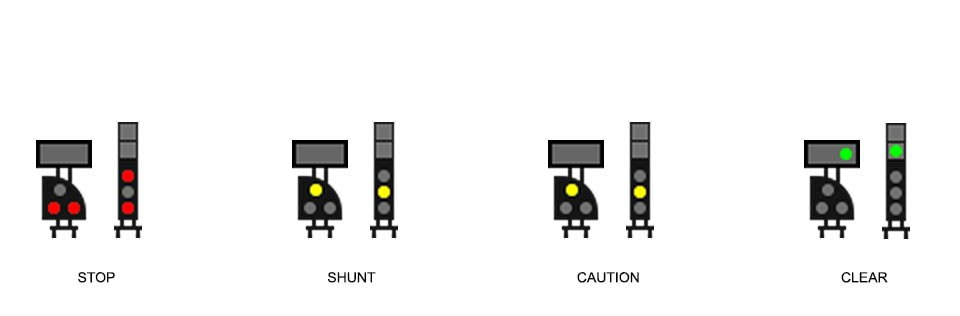
STOP
Stop
SHUNT
Medium
CAUTION
Caution
CLEAR
Proceed
Stop
- Stop, do not pass this signal.
SHUNT
Medium
- Proceed at a restricted speed.
- Do not pass the limit of shunt unless authorised.
- The line ahead may be occupied.
- Points have been set for the route.
CAUTION
Caution
- Proceed, the next signal may be at STOP.
CLEAR
Proceed
- Proceed, the next signal is at least MEDIUM.
Mainline Indicators
STOP
Stop
SHUNT
Medium
CAUTION
Caution
ADVANCED CAUTION
Advanced Caution
CLEAR
Proceed
CLEAR TURNOUT
Proceed Left/Right
Stop
- Stop, do not pass this signal.
SHUNT
Medium
- Proceed at a restricted speed in accordance with the Train Order.
- Points have been set for a diverging route.
- Do not pass the Yard Limits.
CAUTION
Caution
- Proceed in accordance with the Train Order.
- The next MLI is displaying STOP.
ADVANCED CAUTION
Advanced Caution
- Proceed in accordance with the Train Order.
- The next MLI is displaying CAUTION or CLEAR TURNOUT.
CLEAR
Proceed
- Proceed in accordance with the Train Order.
- Line ahead is set for the main route.
CLEAR TURNOUT
Proceed Left/Right
- Proceed in accordance with the Train Order.
- Line ahead is set for the diverging route.
Further Reference
If you are interested in reading more about signalling practices in NSW, the following links may be of use. These cover the more technical aspects of signalling as it applies to the real world.
ARTC - Signals and Signs
https://www.artc.com.au/customers/operations/rules-procedures/nsw/signals-signs/
This page contains the rules relating to signals, indicators and trackside signage used within the NSW rail network.
RailSafe - Driver Route Knowledge Diagrams (DRKD)
https://railsafe.org.au/diagrams/drivers-route-knowledge-diagrams
This page contains diagrams for the Sydney rail network. It is a useful resource for building routes particularly if you are modelling a specific location. The diagrams are representative of the track infrastructure and surrounding areas.
SA Track and Signal
http://sa-trackandsignal.net/?diagram=artc-nsw-din#diagrams
This site is similar to the DRKD but for the regional network. The diagrams are more simplified and focus on track infrastructure for freight operations rather than driver knowledge. They are divided up into the various operational sections of the ARTC network and include some privately operated lines as well.